

Solar Cells
Solar cells are in fact large area semiconductor diodes. Due to photovoltaic effect energy of light (energy of photons) converts into electrical current. At p-n junction, an electric field is built up which leads to the separation of the charge carriers (electrons and holes). At incidence of photon stream onto semiconductor material the electrons are released, if the energy of photons is sufficient. Contact to a solar cell is realised due to metal contacts. If the circuit is closed, meaning an electrical load is connected, then direct current flows. The energy of photons comes in "packages" which are called quants. The energy of each quantum depends on the wavelength of the visible light or electromagnetic waves. The electrons are released, however, the electric current flows only if the energy of each quantum is greater than WL - WV (boundaries of valence and conductive bands). The relation between frequency and incident photon energy is as follows:
[Equ 1]
h - Planck constant (6,626·10-34Js), μ - frequency (Hz)
Crystalline solar cells
Among all kinds of solar cells we describe silicon solar cells only, for they are the most widely used. Their efficiency is limited due to several factors. The energy of photons decreases at higher wavelengths. The highest wavelength when the energy of photon is still big enough to produce free electrons is 1.15 μm (valid for silicon only). Radiation with higher wavelength causes only heating up of solar cell and does not produce any electrical current. Each photon can cause only production of one electron-hole pair. So even at lower wavelengths many photons do not produce any electron-hole pairs, yet they effect on increasing solar cell temperature. The highest efficiency of silicon solar cell is around 23 %, by some other semi-conductor materials up to 30 %, which is dependent on wavelength and semiconductor material. Self loses are caused by metal contacts on the upper side of a solar cell, solar cell resistance and due to solar radiation reflectance on the upper side (glass) of a solar cell. Crystalline solar cells are usually wafers, about 0.3 mm thick, sawn from Si ingot with diameter of 10 to 15 cm. They generate approximately 35 mA of current per cm2 area (together up to 2 A/cell) at voltage of 550 mV at full illumination. Lab solar cells have the efficiency of up to 30 %, and classically produced solar cells up to 20 %.
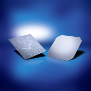
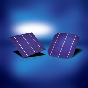
Wafers and crystalline solar cells (courtesy: SolarWorld)
Amorphous solar cells
The efficiency of amorphous solar cells is typically between 6 and 8 %. The Lifetime of amorphous cells is shorter than the lifetime of crystalline cells. Amorphous cells have current density of up to 15 mA/cm2, and the voltage of the cell without connected load of 0.8 V, which is more compared to crystalline cells. Their spectral response reaches maximum at the wavelengths of blue light therefore, the ideal light source for amorphous solar cells is fluorescent lamp.
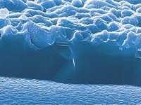
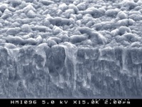
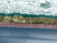
Surface of different solar cells as seen through microscope
(courtesy: Helmholtz-Zentrum Berlin)
Solar Cell Models
The simplest solar cell model consists of diode and current source connected parallelly. Current source current is directly proportional to the solar radiation. Diode represents PN junction of a solar cell. Equation of ideal solar cell, which represents the ideal solar cell model, is:
[Equ 2]
IL - light-generated current [1] (A),
Is - reverse saturation current [2] (A)
(aproximate range 10-8 A/m2)
V - diode voltage (V),
VT - thermal voltage (see equation below),
VT = 25.7 mV at 25°C
n - diode ideality factor = 1...2 (n = 1 for ideal diode)
Thermal voltage VT (V) can be calculated with the following equation:
[Equ 3]
k - Boltzmann constant = 1.38·10-23 J/K,
T - temperature (K)
q - charge of electron = 1.6·10-19 As
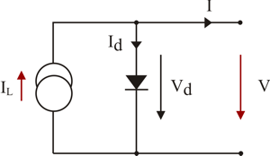
FIGURE 1: Ideal solar cell model
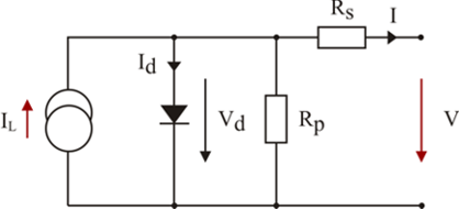
FIGURE 2: Real Solar cell model with serial and parallel resistance [3]
Rs and Rp,
internal resistance results in voltage drop and parasitic currents
The working point of the solar cell depends on load and solar irradiation. In the picture, I-V characteristics at short circuit and open circuit conditions can be seen. Very important point in I-U characteristics is Maximum Power Point, MPP. In practice we can seldom reach this point, because at higher solar irradition even the cell temperature increases, and consequently decreasing the output power. Series and paralell parasitic resistances have influence on I-V curve slope. As a measure for solar cell quality fill-factor, FF is used. It can be calculated with the following equation:
[Equ 4]
IMPP - MPP current (A), VMPP - MPP voltage (V)
Isc - short circuit current (A), Voc - open circuit voltage (V)
In the case of ideal solar cell fill-factor is a function of open circuit parameters and can be calculated as follows:
[Equ 5]
Where voc is normalised Voc voltage (V) calculated with equation below:
[Equ 6]
k - Boltzmann constant = 1,38·10-23 J/K,
T - temperature (K)
q - charge of electron = 1,6·10-19 As,
n - diode ideality factor (-)
Voc - open circuit voltage (V)
For detailed numerical simulations more accurate models, like two diode model, should be used. For additional explanations and further solar cell models description please see literature below.
Solar Cell Characteristics
Samples of solar cell I-V and power characteristics are presented on pictures below. Typical point on solar cell characteristics are open circuit (when no load is connected), short circuit and maximum power point. Presented characteristics were calculated for solar cell with following data: Voc = 0,595 mV, Isc = 4,6 A, IMPP = 4,25 A, VMPP = 0,51 V, and PMPP temperature coefficient γ = -0,005 %/K. Calculation algorithm presented in the book Photovoltaik Engineering (Wagner, see sources) was used.
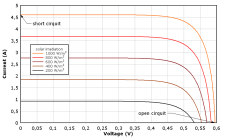
FIGURE 3: Solar cell I-V characteristics for different irradiation values
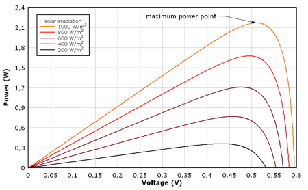
FIGURE 4: Solar cell power characteristics for different irradiation values
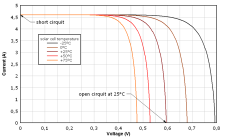
FIGURE 5: Solar cell I-V characteristics temperature dependency
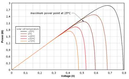
FIGURE 6: Solar cell power characteristics temperature dependency
Notes
| [1] | Sometimes term photocurrent IPh is also used. |
| [2] | Sometimes term dark current Io is also used. |
| [3] | For paralell resistanse term shunt resistor Rsh is also used. |
Simulation Tools
Open Photovoltaics Analysis Platform - Open Photovoltaics Analysis Platform (OPVAP) is a group of software used in the field of solar cells, which include analyzing experimental data, calculating optimum architecture based on your materials, and even some research assistant tools such as PicureProcess.
Organic Photovoltaic Device Model - Organic Photovoltaic Device Model (OPVDM) is a free 1D drift diffusion model specifically designed to simulate bulk-heterojuncton organic solar cells, such as those based on the P3HT:PCBM material system. The model contains both an electrical and an optical solver, enabling both current/voltage characteristics to be simulated as well as the optical modal profile within the device. The model and it's easy to use graphical interface is available for both Linux and Windows.
Other Technologies - Links
NanoFlex Power - flexible organic solar cells.
sphelar power - spherical solar cells technology.
Sources and Additional Information - Books
|
|
Luque,A., Hegedus, S. eds. (2011), Photovoltaic Science and Engineering, Wiley, ISBN 978-0470721698. |
|
|
Wenham, S., Green, M.A., Watt, M., Corkish, R. (2011), Applied Photovoltaics, Earthscan, ISBN 978-1849711425. |
|
|
Wagner, A. (2009), Photovoltaik Engineering: Handbuch für Planung, Entwicklung und Anwendung, (VDI-Buch); Springer, ISBN 978-3642054129. |
Papers
|
|
Green, M. A. (1981), Solar cell fill factors: General graph and empirical expressions, Solid-State Electronics, vol. 24, issue 8, pp. 788 - 789. |
|
|
Green, M. A. (1982), Accuracy of analytical expressions for solar cell fill factors; Solar Cells, 7, pp. 337-340. |
|
|
Easwarakhanthan, T. Bouhouch, L. Bottin, J. Nguyen, P.H. (1985), Semiempirical expressions for solar cell fill factors; Electronics Letters, Volume: 21, Issue: 12, p.529-530, ISSN: 0013-5194. |